A DIY SDVX/K-Shoot Mania Controller Guide
Last Updated: 3/24/2019
Table of Contents
- About SDVX
- Controller Options
- Equipment List
- Parts List
- Limit Switches
- Box Assembly
- Electrical Assembly
- Programming
- Completed Controllers
- Troubleshooting
- Contact Me
About SDVX
Sound Voltex is a rhythm game that originated in Japan. It mixes the standard top down four column layout of other rhythm games along with two additional columns which overlap on columns 1/2 and columns 3/4. It also incorporates two effects sliders which cross the playing field. Sound Voltex arcade machines are playable in Japan and in the United States through Round1. A PC application available for most countries as Sound Voltex III e-AMUSEMENT CLOUD.
K-Shoot Mania is the main alternative to SDVX and is free to play and supports a wide variety of input control schemes. The K-Shoot Mania Project can be found here.
Controller Options
Before you decide to build your own controller, it may be worthwhile comparing existing options. Building your controller is a rewarding experience but will often cost as much or more than commercial controllers, especially if you don’t already have access to the necessary tools.
Equipment List
One of the biggest obstacles to actually building the controller is having access to the necessary equipment. If you don’t have access to the equipment at home or at a university, check to see if there’s a hacker space nearby which might have the equipment you need.
If you have access to computerized equipment such as a laser cutter, you will be able to cut square holes and recess the buttons into the top plate of the controller. If you only have access to standard wood working tools, the buttons will have to sit on top of the top plate which only affects aesthetics and not performance.
- Laser Cutter or CNC Mill
- Soldering Iron
- Spade Crimping Tool (or pliers)
- Wire Cutter
Parts List
For most builds, I would recommend using Chinese clones over official Sanwa parts due to the steep cost of Sanwa parts. The parts which affect gameplay performance the most are the limit switches and the optical rotary encoders.
Some parts in the parts list can be substituted with other parts depending on your preferences. Please read the limit switch weighting section to determine which limit switch weighting is right for you.
Controller w/Clone Buttons ($140):
- $20.00 4x 60mm Square Arcade Buttons
- $8.00 2x 45mm Rectangular Arcade Buttons
- $1.50 1x 33mm Square Arcade Buttons
- $10.00 1x Arduino Micro
- $7.50 1x Arduino Micro Breakout
- $10.00 4x 100g Basic Limit Switches (Optional but Recommended)
- $6.00 3x 50g Basic Limit Switches (Optional but Recommended)
- $7.50 1x 100pc Spade Connector (Optional but Recommended)
- $20.00 2x Optical Rotary Encoders
- $15.00 2x 6mm D-Shaft Aluminum Knobs
- $10.00 1x 48”x24”x1/4” Medium Density Fiberboard (Try to Source Locally)
- $20.00 1x 18”x12”x1/4” Clear Acrylic (Optional & Try to Source Locally)
- $5.00 1x Micro USB B 2.0 Cable (May be included with Arduino)
Controller w/Sanwa Buttons ($277):
- $80.00 4x 60mm Square Sanwa Buttons
- $30.00 2x 45mm IIDX Sanwa Buttons
- $10.00 1x 33mm Square Sanwa Buttons
- $56.00 7x LED Holder
- $7.50 1x Arduino Micro Breakout
- $10.00 4x 100g Basic Limit Switches (Optional but Recommended)
- $6.00 3x 50g Basic Limit Switches (Optional but Recommended)
- $7.50 1x 100pc Spade Connector (Optional but Recommended)
- $20.00 2x Optical Rotary Encoders
- $15.00 2x 6mm D-Shaft Aluminum Knobs
- $10.00 1x 48”x24”x1/4” Medium Density Fiberboard (Try to Source Locally)
- $20.00 1x 18”x12”x1/4” Clear Acrylic (Optional & Try to Source Locally)
- $5.00 1x Micro USB B 2.0 Cable (May be included with Arduino)
Possible Part Substitutions:
- $2.50 2x PEC16 Mechanical Encoder (Replace Optical Encoder)
- $5.00 4x 0.1uF Capacitors (Required for Mechanical Encoder)
- $10.00 7x 25g Basic Limit Switch (Use if Keeping Button Return Spring)
Limit Switches
Choosing Your Limit Switch Weight
Arcade buttons will usually ship as a preassembled unit containing the arcade button, limit switch, LED lamp holder, LED fixture and LED. These arcade buttons typically come with really heavy return springs (100g - 150g) and heavy limit switches (100g - 200g). Using both of the default parts will probably be too heavy to play difficult songs with and I would recommend using either of the three following configurations.
The first recommended configuration is to completely remove the heavy return spring and to use a medium weighted limit switch. This configuration offers a light actuation force and tactile feedback upon actuation. This configuration only requires you to buy new limit switches which should be 100g - 150g for the 60mm buttons, 50g - 75g for the 45mm buttons and 50g for the 33mm buttons. You could try out this configuration with the default limit switches but these no-name Chinese switches often have a high snap-over value which causes the return force to be very weak. I recommend using Omron or Honeywell limit switches instead.
The second configuration is to keep the heavy return spring and use a lightly weighted limit switch. This configuration offers a consistent actuation force throughout the button press but has a somewhat high overall actuation force. This configuration however will be more responsive button return than the previous configuration. Since very light limit switches are very hard to find and are often very fragile, the lightest reliable switch will probably be 25g Omrons.
The third configuration is to replace the return spring with a lighter spring and limit switch. This configuration is a compromise between the previous two configurations offering the best traits of both which is a relatively light actuation force and a responsive feel to the button. This configuration is also the most expensive since you have to buy both return springs and limit switches. Return springs are hard to find and springs from Japan are often expensive with shipping.
Custom Button Weighting
This chart displays the weight of the individual parts of the button which the switch must act against and the minimum force buffer that you must maintain for correct operation. The actuation force is roughly the summation of the return spring and the actuation force of the limit switch. The minimum actuation force required is a suggestion however choosing a lower actuation force will result in buttons which return slowly creating a sluggish feel.
Official Sound Voltex Arcade machines do not have a universal weighting for the buttons and often vary between arcades.
| Button Size | Plunger Weight | AF* w/Spring | AF* w/Spring & 25g Switch | Minimum Switch AF* Required |
|---|---|---|---|---|
| 60mm Square | 22g | 290g | 330g | 150g |
| 45mm Rectangle | 7g | 150g | 180g | 100g |
| 33mm Square | 3g | 150g | 170g | 50g |
AF*: Actuation Force
Box Assembly
Design
For the box design, we will use a layout that was originally sourced from sdvx.pancakeapps.io. Unfortunately, I have only designed boxes for use with laser cutters and if you are building a box without precision equipment, you will have to design your box from scratch.
If you have access to a laser cutter, I have created design files for two types of boxes. The standard design uses 1/4” thick medium density fiberboard for the box and uses finger joints to maintain structural integrity. The other design has a clear acrylic sheet on the top and has a MDF plate underneath it which allows for underglow lighting. This tutorial will uses the standard design without LED lighting.
- Standard Design (GitHub)
- Underglow Design (GitHub)
MDF was used as the main material for the standard design due to its strength, low cost and ease of painting. MDF however is a fairly dense wood and takes many passes with a laser cutter (8 passes in my case) and can be substituted for a different type of wood. Acrylic can also be substituted for MDF however, make sure you do not use polycarbonate as polycarbonate will create toxic gasses when laser cut.
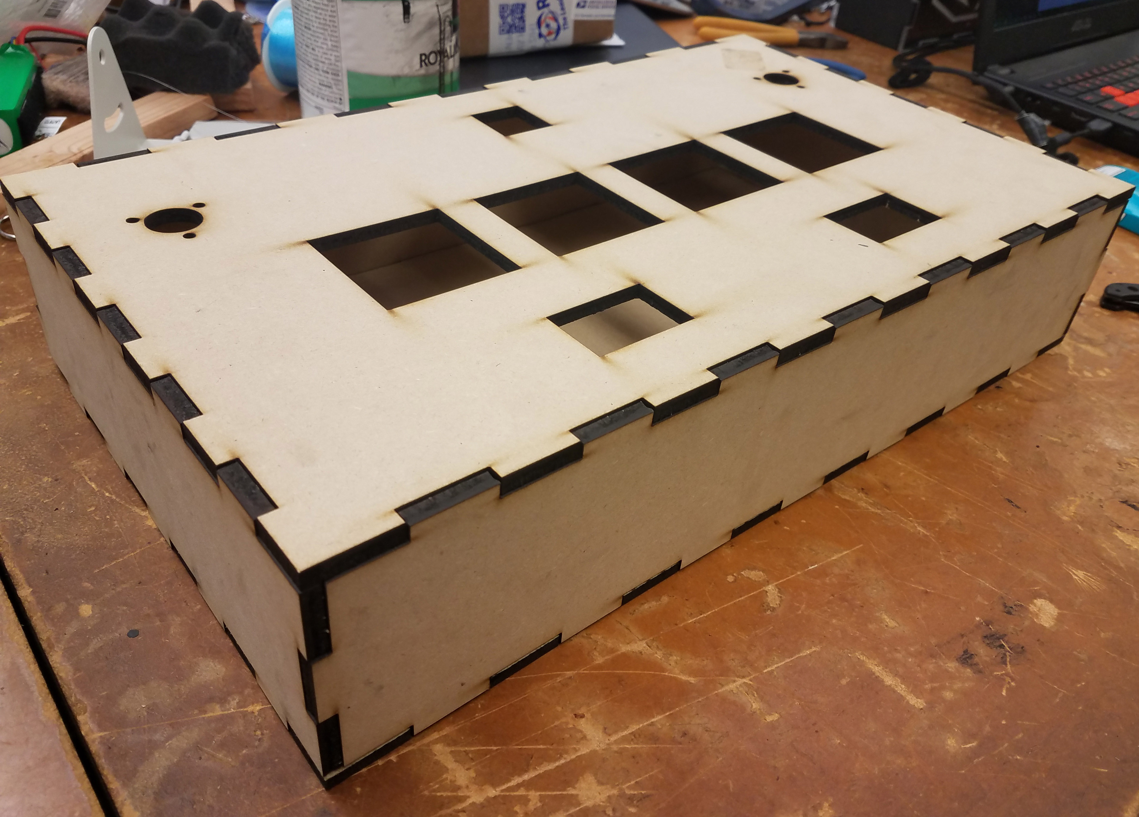
Standard Box Design
Painting
Since the standard design uses wood, regular oil based paint can be used. If you are using some type of plastic such as acrylic or polycarbonate, you will need to use a non-oil based paint such as acrylic paint. If oil based paint is used on acrylic or polycarbonate, the paint will dissolve the plastic.
Caution: Acrylic paint often contains latex which can cause allergic reactions!!!
Gluing
Although the design was laser cut with finger joints, due to the variance of the size of the laser between laser cutters, it is unlikely that the panels will friction fit. To hold the panels together, we will glue to the side panels and the bottom panel together. Silicone or epoxy is recommended as it is strong and allows for some adjustment as it cures. Both types of glue will typically take at least 24 hours to cure. Use painters tape or fishing wire to hold the panels together while the glue cures.
To prevent the side panels from angling inward and preventing the top plate from fitting, place the top plate onto the box while the glue is curing. Make sure that there is no glue touching the top plate or you will have to either break the bond later or remake the side panels.
Top Plate Placed on Box to Set Alignment While Curing
Electrical Assembly
Arcade Button Overview
The arcade buttons consists of eight main parts, the housing, plunger, plate mount, fastener, LED lamp, lamp holder, return spring and limit switch. An layout of the different parts can be found below.
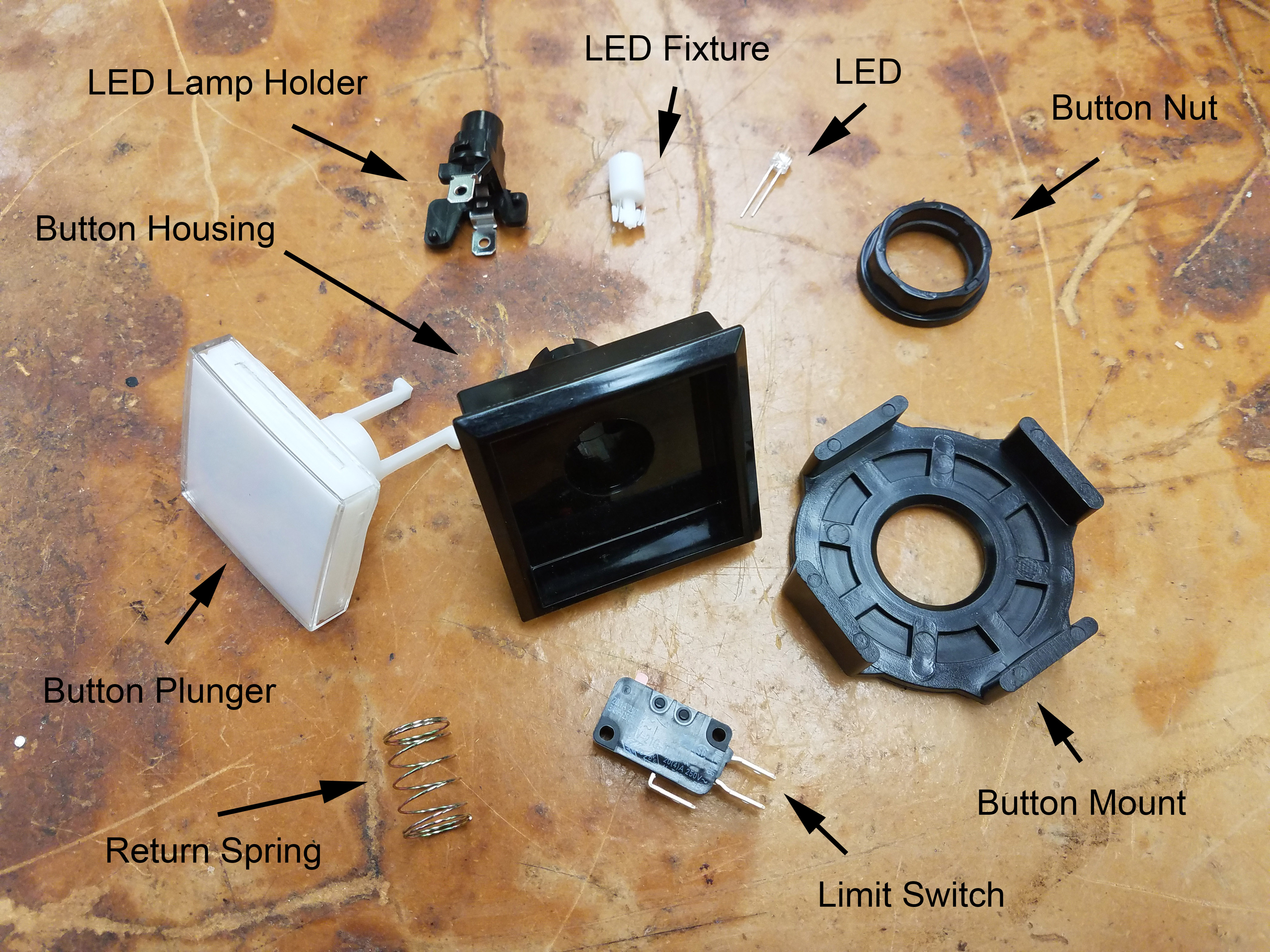
Overview of Arcade Button Components
Arcade Button Return Spring Removal
If you are using a button configuration where the return spring must be removed, you will need to disassemble the arcade button. To disassemble the button, remove the limit switch and LED lamp from the button. Twist the lamp holder counter-clockwise to unlock and pull to remove. To remove the plunger, squeeze both plunger tabs inward and push the plunger out. Once the plunger is removed, you can replace or remove the return spring.
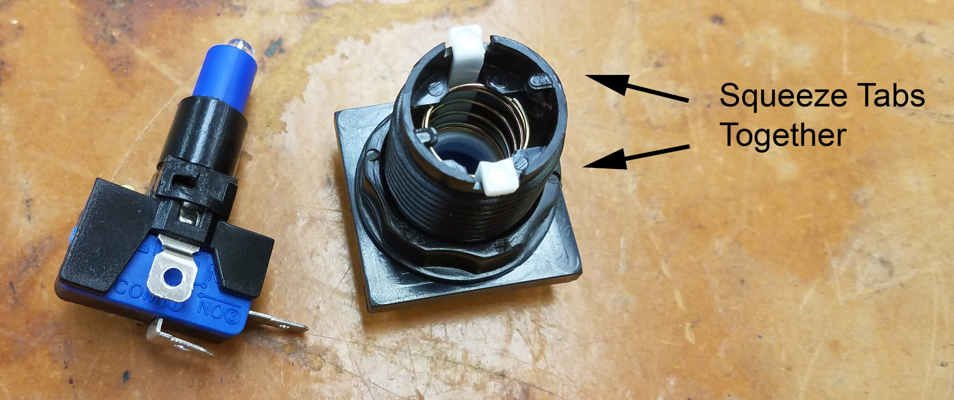
Plunger Removal
Switch & LED Lamp Wiring
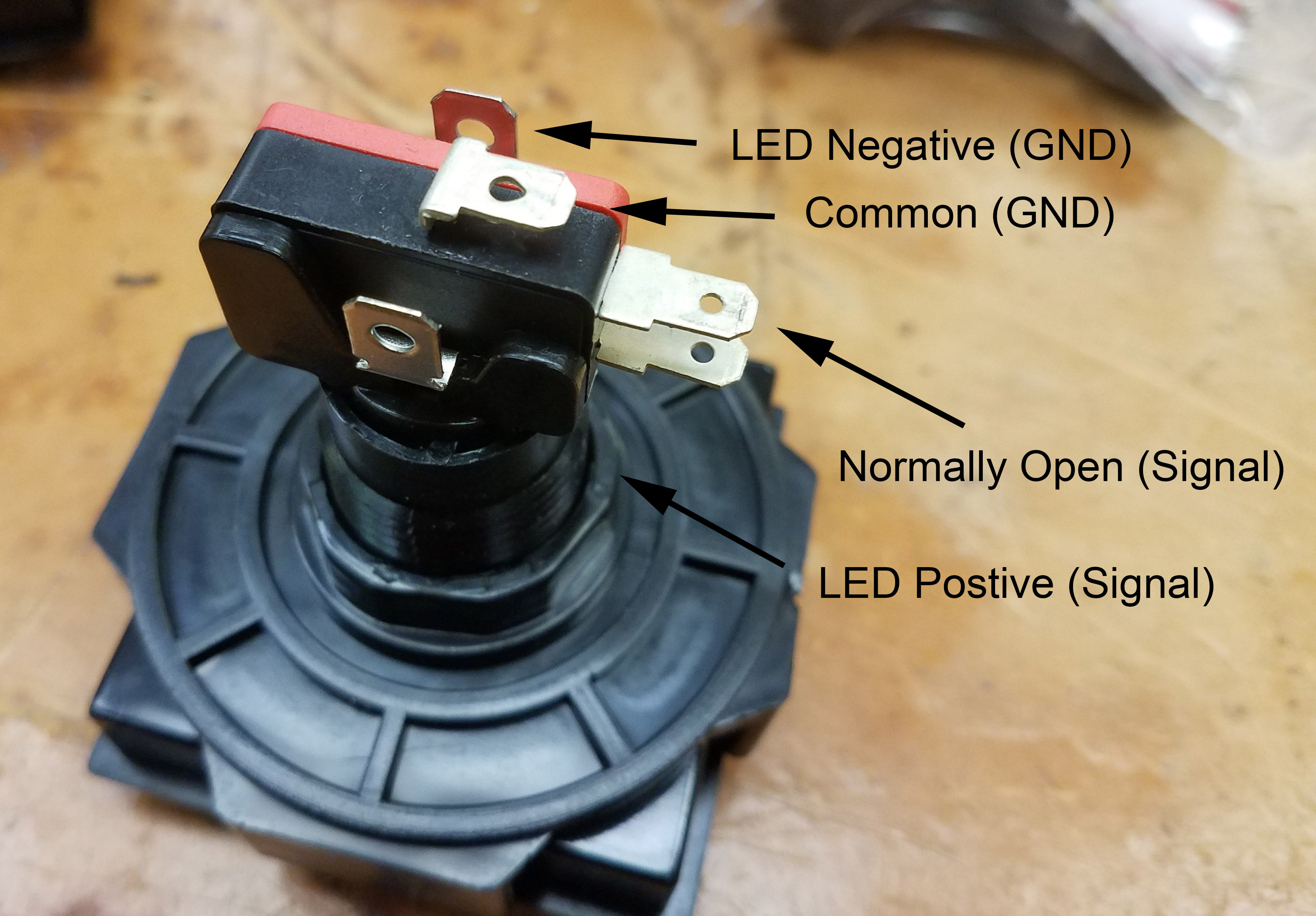
Arcade buttons usually ship with a lamp holder, LED fixture and LED. The LED will either be white or the same color as the button cap. Most of the LED fixtures and LEDs that ship with the arcade buttons will have a resistor soldered to the LED in the fixture. This allows the LED to be driven directly off 12V without a resistor. Since we will be driving the LED directly off the output pin of an Arduino, the LED will be dimmer than intended. The LEDs chosen for the guide are a flat topped variety which offers the best illumination pattern within the square button and can be driven directly off the 5V output pin without an external resistor. The side of the lamp which has longer leads or more wire wrapped around the bottom post is the positive side of the LED.
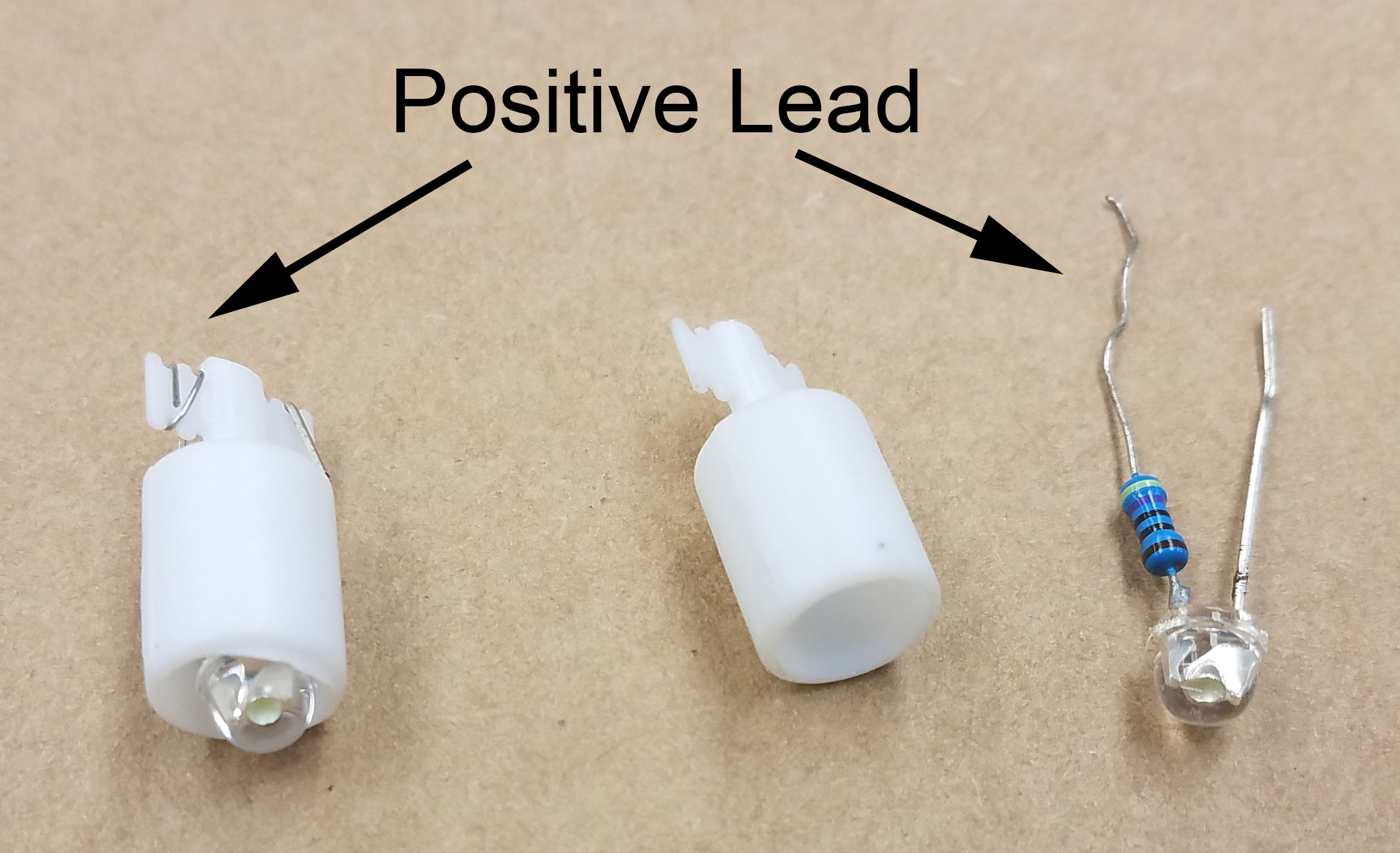
Assembled LED & Holder (left) & Disassembled (right)
Create Limit Switch & LED Signal Wires
For this section, you will need 14 45cm lengths of wire, 14 spade connectors, a wire cutter, wire stripper, crimping tool and soldering iron.
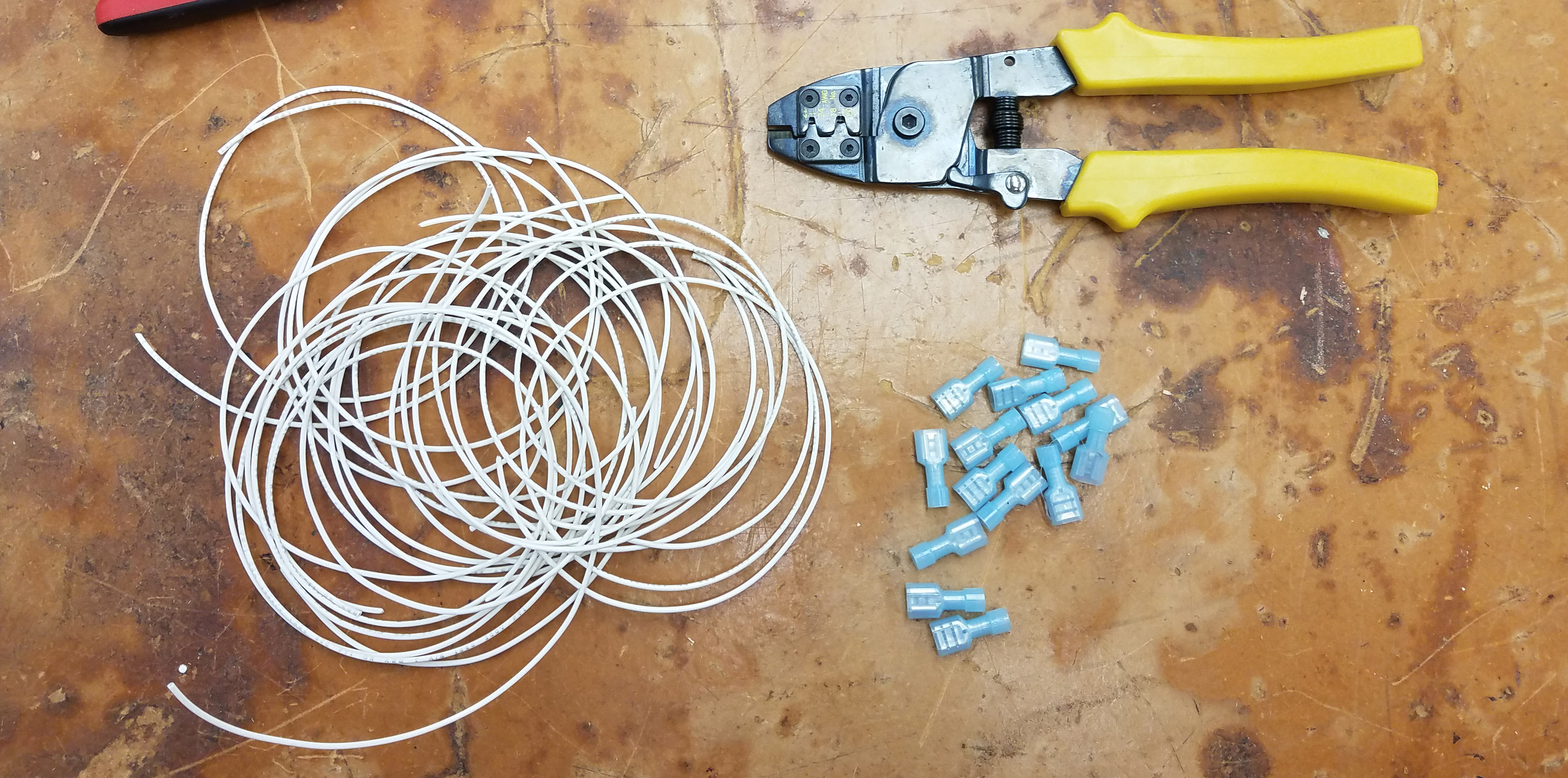
Signal Wires, Spade Connectors & Crimper
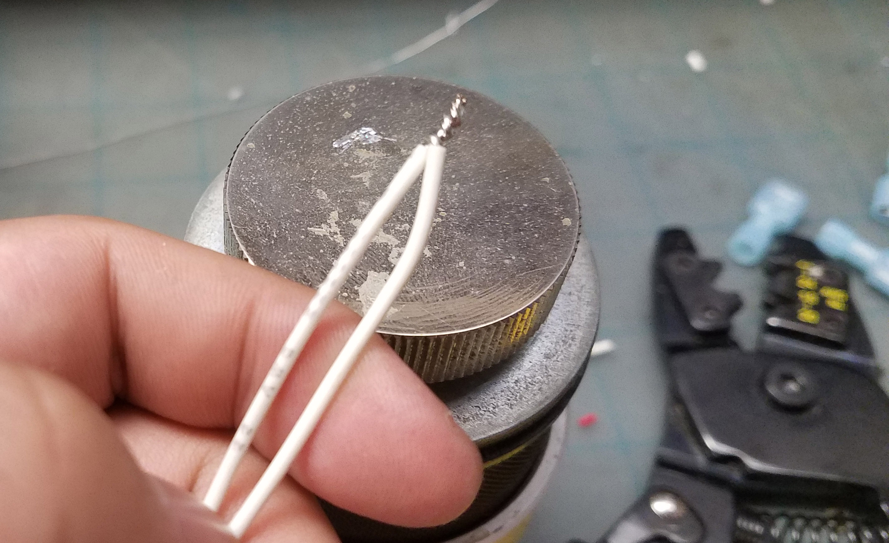
Using your wire stripper, strip off about 5mm of insulation off both ends of each wire. Once all of the wires are stripped, use your soldering iron and tin both ends of the wire. The ends should be coated in a light application of solder and the individual wire strands should not separate.
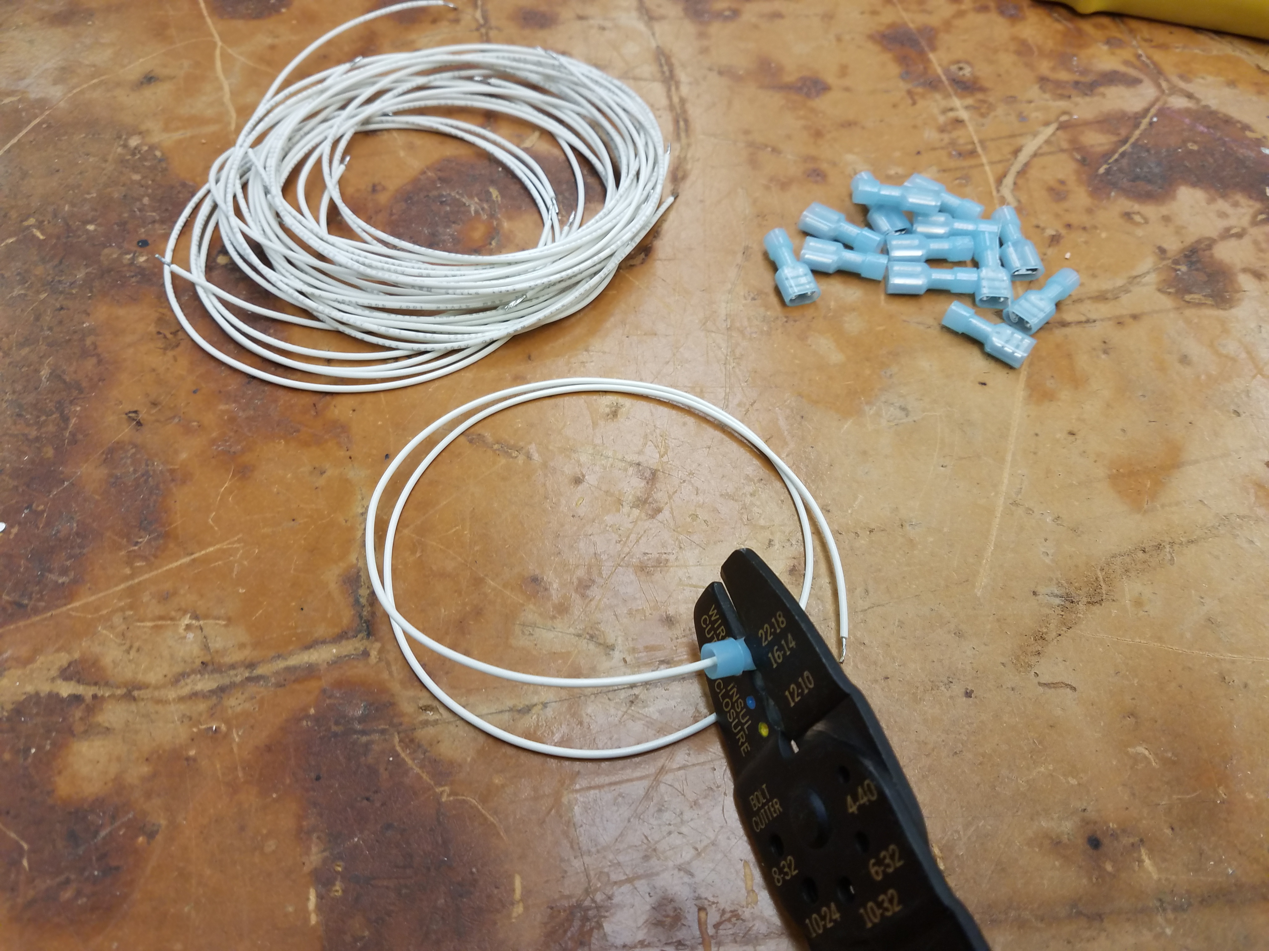
Using Crimping Tool To Crimp Spade Connector
Once you’ve tinned both ends of the wire, use a crimping tool to attach one spade connector to each wire. There should only be one spade connector on each length of wire.
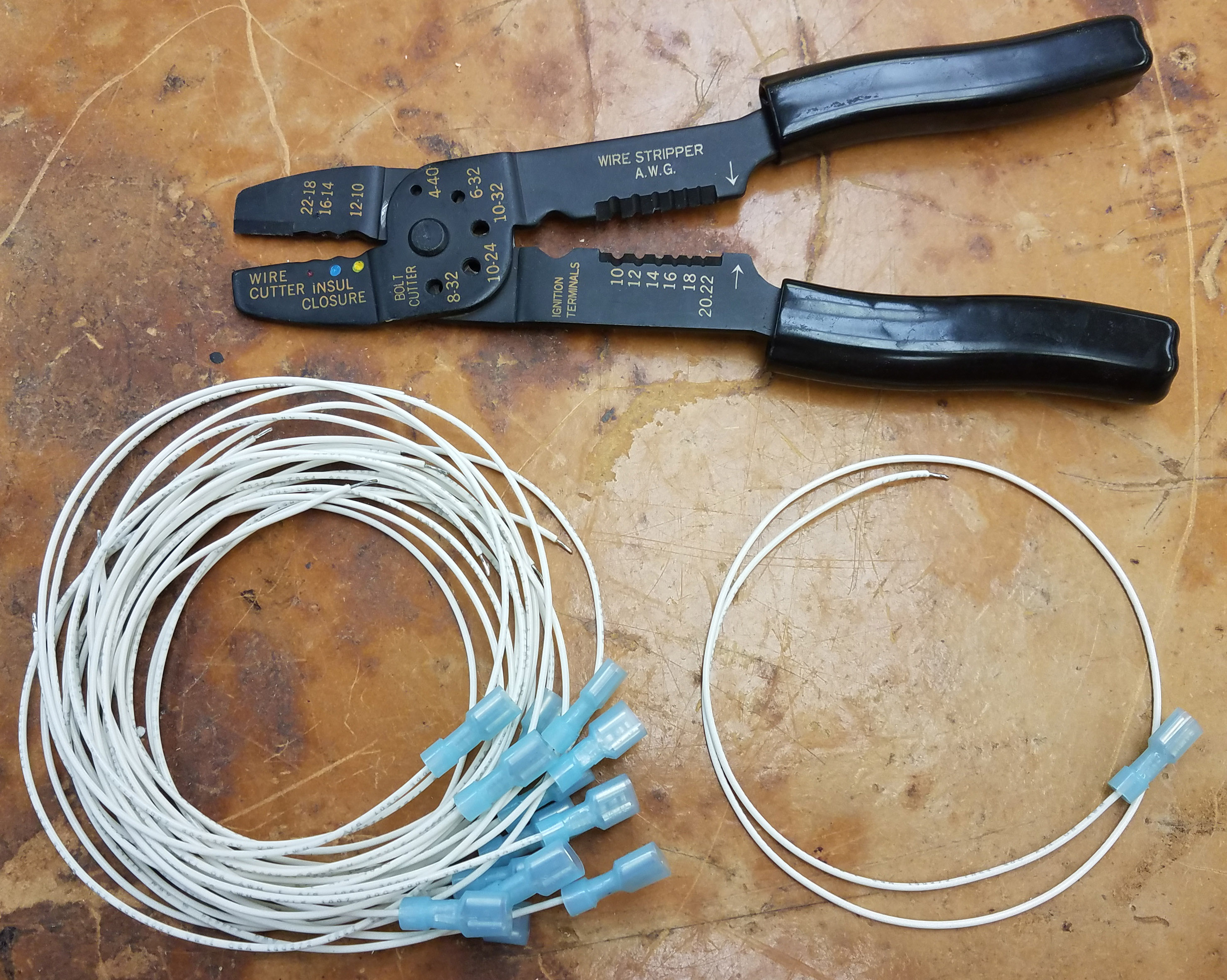
Finished Signal Wires
Create Ground Harness
For the ground wire, we will create a single daisy chained wire (harness) to connect all of the grounds. This allows us to reduce the number of wires in the box by half.
To reduce the length of excess wire, we will measure the length of wire by measuring the space between the buttons. Unlike the signal wires, two wires will have to be soldered together first before the spade connector can be crimped.
Soldering Ground Harness Wires
One terminal on both the limit switch and the LED lamp holder will connect to ground. The normally opened (NO) pin and the terminal of the LED lamp holder with less plastic. Each of the soldered wires will need to be crimped. You should need a total of 14 spade connectors for the ground harness.
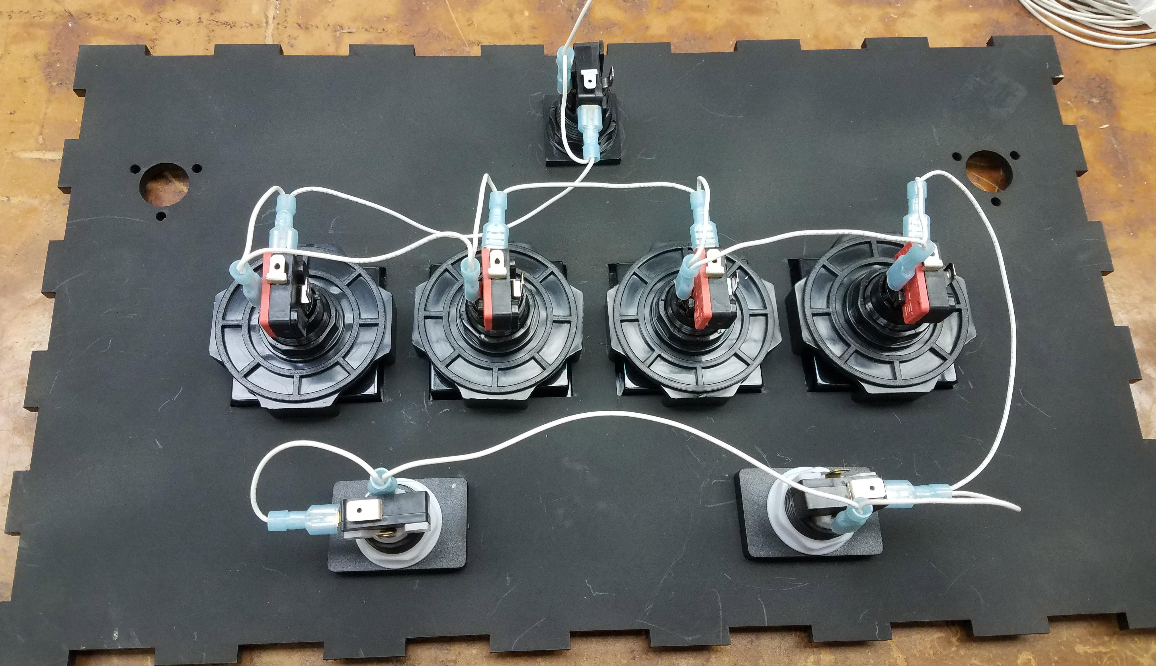
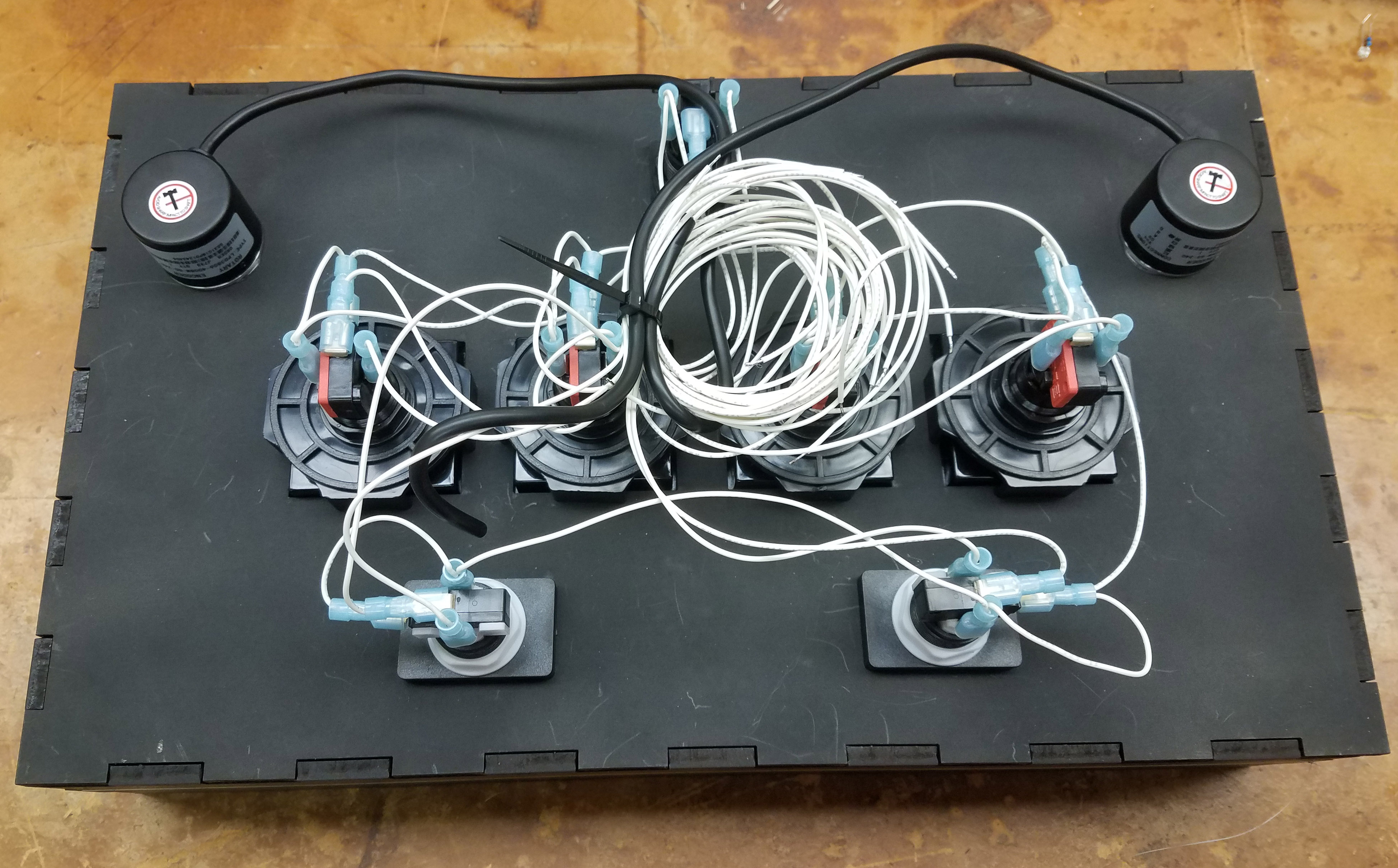
Ground Harness Wired onto Buttons
Rotary Encoder Wiring
The rotary encoder used in this guide is an optical type encoder which offers high resolution and a smooth rotation. Optical rotary encoders will usually come with four wires which are 5V, GND, D+ and D-. Since the Arduino Micro only has one 5V pin and two ground pins, you will have to solder the 5V and ground wires of the two rotary encoders together. The D+ and D- are the signal wires which send pulses to the Arduino Micro. After connecting the wires to the Arduino Micro, if the direction of encoders are reversed, switch the D+ and D- wires.
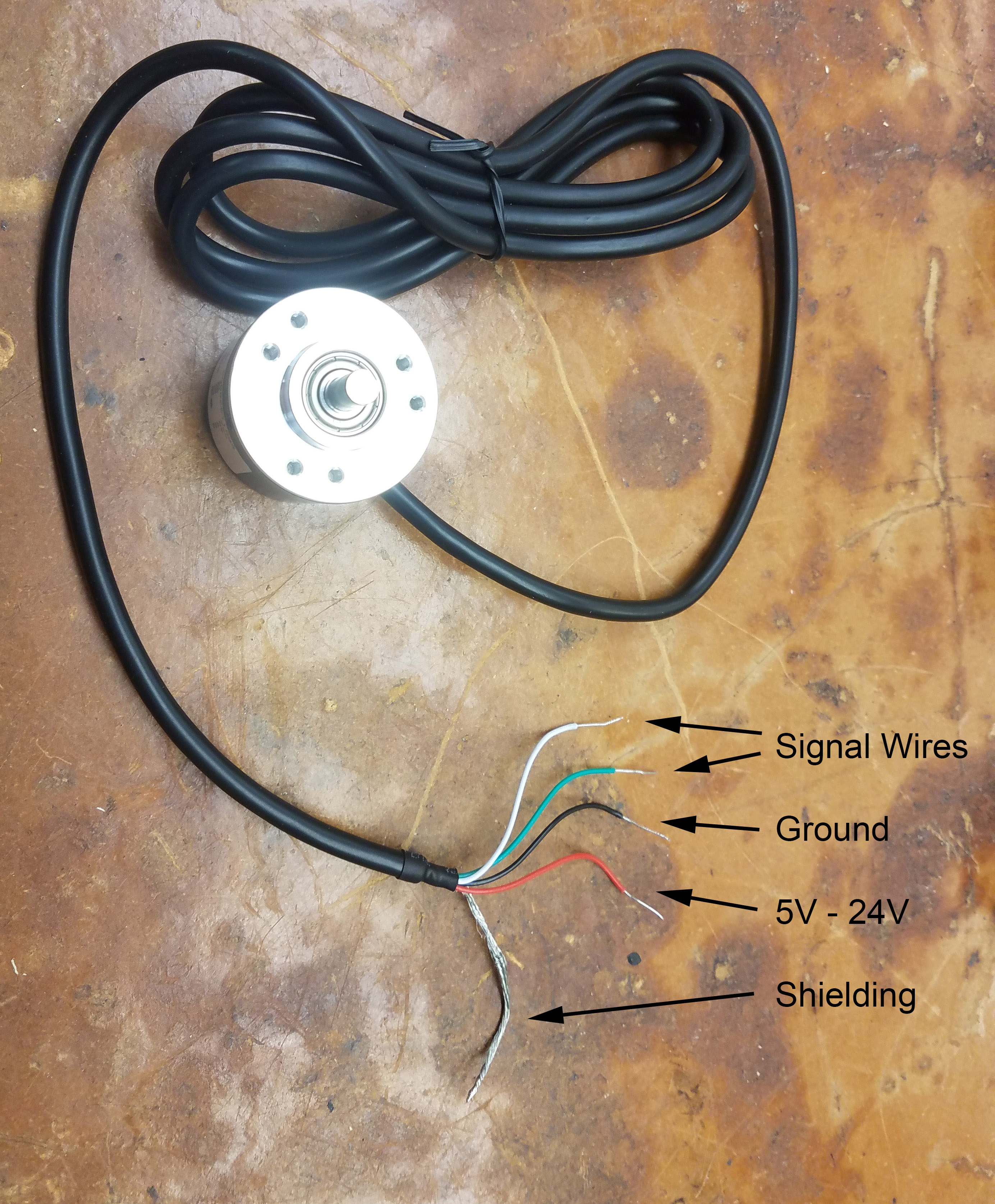
Encoder Pinout
If you are using mechanical encoders, then the outer two pins are D+ and D- and the center pin is ground. Mechanical encoders are not active devices and do not require 5V supply. Similarly to the optical encoders, if the direction is reversed, you can swap the data pins to reverse the direction. Mechanical encoders however do suffer from switch bounce which will affect the signals being sent to the Arduino. To mitigate this, wire a 0.1uF capacitor between the D+/D- and ground.
Arduino Wiring
In this guide, we used an Arduino Micro with a breakout board instead of the more traditional Arduino Leonardo. While this route is slightly more expensive, the screw terminals on the breakout board are a more permanent solution than plugging wires into a pin header.
Limit Switch and LED Pins
As of writing, the wiring for the buttons should be plugged into the following ports on the Arduino Micro’s breakout board.
| Button | Limit Switch Pin | LED Pin |
|---|---|---|
| BT-A | A2 | 9 |
| BT-B | A3 | 10 |
| BT-C | A4 | 11 |
| BT-D | A5 | 12 |
| FxL | A0 | 5 |
| FxR | A1 | 6 |
| Start | 7 | 13 |
| Encoder | D+ Pin | D- Pin |
|---|---|---|
| Left | TX (0) | RX (1) |
| Right | 2 | 3 |
These pin assignments can be adapted to the Arduino Leonardo or any other Keyboard & Mouse library compatible boards. Make sure encoder pins are assigned to interrupt pins if a different board is used.
Programming
Installation
In order to load the firmware onto the Arduino Micro, you will need to install the Arduino IDE. If you already have the Arduino IDE installed, make sure it is the latest version as older versions handle libraries in sketch folders differently.
Downloading the Code
The firmware code can be found in my SDVX-DIY GitHub repository. There are two main development branches, master and standard. The standard branch is the branch used for this tutorial. The master branch has SK6812 based RGB LED backlighting which is not covered in this tutorial.
Standard Firmware
RGB Firmware
To download the code, navigate to the appropriate branch and click the “Clone or download” dropdown and download as a zip file. To open the code, unzip the downloaded zip file and open the “SDVX-DIY.ino” file with the Arduino IDE.
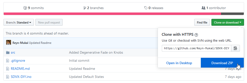
Downloading The Code
Uploading the Code
Before you upload the code, there are several parameters within the code that can be modified in the event that different parts or wiring was used. View the GitHub readme on each branch’s respective page for further information.
To upload the code, you will first need to select the board type and COM port of your controller in the Arduino IDE. To select the board type, navigate to the “Tools” dropdown, expand the “Board:” option and select your Arduino board. If you are using a Pro Micro, select the Arduino Leonardo board. Next, on the “Tools” dropdown, expand the “Ports:” option and select your controller’s COM port. Once these settings are set, click on the arrow on the top left of the screen to upload the program.
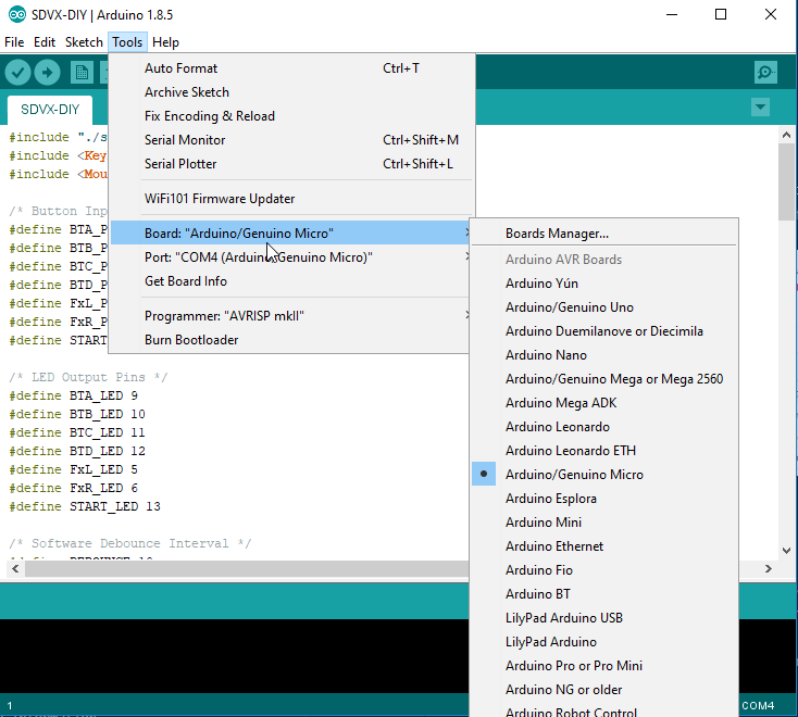
Selecting Arduino Board Type
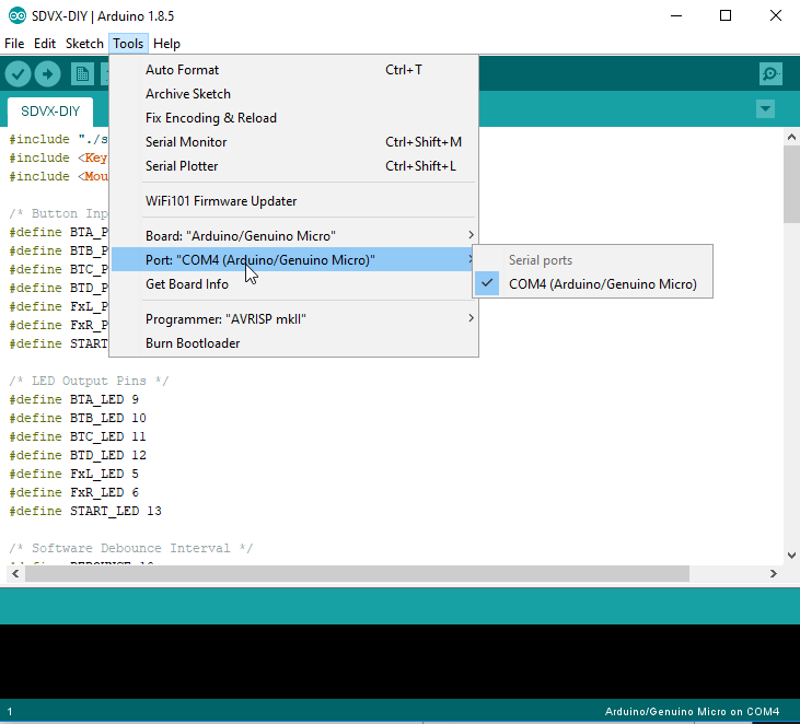
Selecting Arduino COM Port
Completed Controllers
If you followed this guide and completed a controller, feel free to send it in for display.
Troubleshooting
Error out of sync when programming the Arduino:
If you’re getting this message, make sure you COM ports and board type is correct. You may need to hit the reset button as you upload the program.
Contact Me
If you have any questions regarding the guide or have any suggestions on how it may be improved, feel free to contact me at reyn.mukai@gmail.com